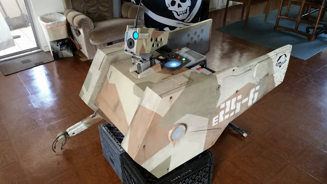
Thursday, October 13, 2016

D-walker build - Conclusion

Videos of final assembly and AHCC '16 costume contest, and reflections on resourceful cosplay.


I had wanted to make this style of costume for a long time.  About 3 years ago, I was sketching plans for a Megaman X2 ride armor costume.  The mech's arms and legs would be mine, I would wear a Megaman helmet, and a little pair of puppet arms would appear to be controlling the mech.


I thought it would be fun to give life to the mech's limbs, and my oversized head next to the tiny little arms would faithfully represent Megaman's art style.  However, the whole thing is made of curves and the legs are reverse jointed.  For these reasons I never got past the brainstorming stage.  I like to keep things simple.

Then MGSV trailers started showing up, and I recognized that D-Walker would be a much easier and more appropriately designed candidate for this project.  Then I started my Snake arm project and MGSV came out, and I'm only barely exaggerating when I say I spent Q4 of 2015 doing nothing else.  I burnt out on the arm project and didn't make anything for a couple months.  Eventually I heard about Amazing Hawaii Comic Con coming in June, and I remembered D-Walker.  I envisioned an ultra-simple build, but as I dug deeper into my junk bins, it got more and more complicated.

From April to June 19th I devoted most of my time to D-Walker.  Below is the final assembly before the con.  It's about 3 hours condensed into 3 minutes.


Somewhere in the middle of that I add some red vinyl and weathering to the side panels, then glue the middle section to the handlebars.  This helps bring the middle pieces together and seals up a large gap near the grips.  This also makes the middle panels the only foam that is no longer removable - the side panels are still attached with zip ties only.

On the way to the convention in a Scion xB with a couple inches to spare.

A few hours after that, I entered D-Walker in my first costume contest and won best in show.  Hooray!  Here is a video of that, in which I awkwardly trot around and attempt to leave the stage before they're done with me.  I also did a bit where I pretended my electronics shut down and then came back on with a well-placed smack.  Unfortunately I accidentally left them turned off, so that was kind of lame.  I show up at 16:00:


The prize was a huge, hammerhead shark-themed great axe.  I couldn't even carry it and operate DW at the same time.  It is now displayed on the wall of my wife's burger shop Burgers and Things, which also has tons of other cool comic and video game art donated by their adoring customers.

The bad ass Shredder won last year's contest, but he had to wait until the con came back this year to collect his prize.

The most rewarding aspects of making this costume was not winning the costume contest or showing it off or even admiring the finished product.  For me, the process was the most enjoyable stage.  Digging through my bins and finding old scraps of plastic and metal takes me back to when I played with Legos in the exact same way.  No matter how mundane an item's history, for some reason my brain has a section devoted to cataloging them.  I know when the perfect piece is hiding at the bottom of the bin, stashed away years ago, before its specific value was apparent.  

D-Walker is a culmination of finding purpose for such items, and in a way, working on it was like tying off loose mental strings.  At any given time I can look at myself a year or even a month ago and chuckle at how naive I was, at the odd decisions I made, at how much I have learned since then.  But whenever I uncover a scrap of metal that I saved from ending up in a landfill some years ago, my seemingly irrational behavior back then is justified.  I can reach back in time and commend myself for saving the skeletal remains of a cheap inkjet printer, because by some stroke of resourceful thinking and/or luck, today those remains are exactly what I needed.   It's kind of like a manageable form of hoarding - I squirrel away this or that just in case I need it some day, just because it may have some conceivable value to someone somewhere sometime.  But a collection needs to be organized and inventoried, or it stops being an asset and becomes a burden.  And unlike a serious hoarding disorder, those loose ends I had collected were eventually utilized.  

Productively liquidating a collection of garbage is a good feeling, especially while building a cool robot costume from one of my favorite video game series, and all at relatively small expense.  After I finished D-Walker, I gave away the rest of my junk to other crafters, in hopes it would be useful to them too.  I was still left with some stuff that no one wanted, and I was a little remiss to trash it.  It was still just a bunch of junk though, some of which I have actually shipped from Hawaii to Oregon to Hawaii once before.  When I move back to Oregon with my wife next year, I want to start with a clean slate.  At least until I have a bunch of empty, easily accessible and labeled storage bins set up in a garage workshop - then I can start scavenging Craigslist free ads and roadside garbage again!

Thanks for reading!  I hope it was helpful and/or interesting.  Now go build something!


Wednesday, October 12, 2016

D-walker build part 5 - Electronics

The real and fake electronics in D-Walker.  These parts used an excessive amount of scavenged parts, so I'll try to save all that source information for a big list at the end.


The "cockpit" of D-Walker is the most detailed part of the costume, even though the rider is about the only person who can really get a good look at it.  That may be for the best, though, because it is also the least accurate part.  Compare the above to the source below:


The proportions just wouldn't have worked with how I wanted to build it.  The real D-Walker is larger than mine, and that big rectangular shape would hinder my legs.  The grips are of suitable size, but I couldn't position them far enough apart without scaling the entire build up.  I also had some electronics from the 80's that I thought would look good, even if they weren't accurate.  I condensed the layout a little to make it work with the scale and materials available.

Anyway, D-Walker has a few simple electronics in it.  In the head it has two LEDs and an exhaust fan, as well as the GoPro Hero 3.  There is a pair of fog lights on the front.  There are some lights and a semi-functional attitude sensor on what we'll call the dashboard (the part with the large blue circle).  The center console has an LED readout of volts and amps, and hidden behind it are a pair of PC fans that blow on the rider's wrists.  The right grip holds the main power switch, and a sub-power switch bank is located to the right of the center console.  At the con, I hid my phone deep in the cockpit using a magnetic mount so I could control the GoPro and do other phone things while appearing to be fiddling with integrated controls instead of my phone.  The four buttons on the sub-power panel control the head lights, head fan, fog lights, and rider fans.

The knobs on the power supply panel are just for show.  Why would a rider need to adjust the current and voltage?  Maybe this is a prototype D-Walker that needs tuning, or maybe it needs to be adjusted when using something like the H-Discharger.  The three switches in front of the right grip are for show because Alan Tudyk loves flipping magic switches.  The black ignition button on the right grip is not currently used, but the plan was to have that be the trigger for whatever weapon is installed on DW's left.  The wiring exists, but I didn't build any weapons.


The red stripes are supposed to remind you to keep your fingers out of the fans.  Sorry for bad lighting.

The above photo is the center console panel, opened for access to the battery pack and power display.  The rider cooling fans make up the left and right walls of this compartment.  A 12V battery pack, modified to make 9 volts, is secured by a twisty wire tie and can be connected/disconnected without removing it.  A length of coat hanger loosely zip tied to the panel acts as a kick stand to hold it open.  A magnet on the lower left holds the panel closed, provides a secure base for the kickstand, and also holds a hex wrench that is needed to remove the head and arm.  I removed the printed circuit boards behind the power supply's display and replaced it with my own self-contained LED display.

Nearly everything about the center console is improvised.  I had already made the frame without knowing exactly how I would build this area, so when I started adding pieces, I just had to make it up as I went along.  While figuring out how to mount the power supply panel, I realized it could be hinged instead of fixed.  The fans were added because they happened to be the perfect size and I thought it was cool, even if they don't actually provide much cooling.  The panel kept slamming shut whenever I bumped it, so I added the kickstand.  I added the LED display when I realized a name tag from my portal gun project would fit in the space and could easily be programmed with whatever I wanted.

Dashboard.  The markings on the blue screen are meaningless now, but they look cool.

The dashboard consists of a green main power light, a red warning light, a DC milliamps meter, an attitude sensor, and some non-functioning buttons and knobs.  The warning light is just a reflector - it's shining here because I used a flash.  The main power light and sensor come on with the main power switch.

An attitude sensor displays a vehicle's pitch and roll as compared to the horizon - this is generally only used in things that fly, and is probably called something else in that application.  In MGSV, the green circle might be a radar or something.  In my D-Walker, however, it came to be an attitude sensor because I was just trying to come up with an interesting way to use that blue screen.  The white LED beneath the plastic screen is affixed to a metal rod with a weight on the bottom, suspended by a water balloon (yes, really).  The water balloon, being nice and flexible, lets the rod sway all over the place.  The rod came out of a printer and has a little groove in it where the water balloon ties around it, keeping it from slipping loose.  The weight, a brass fitting, keeps the rod pointed towards the ground, with an inverse effect on the LED.  You know what, just observe this gif:

A textbook(?) example of a cheap cosplay trick.

I didn't use any relays, resistors or anything complicated in these electronics.  I just made sure all of the LEDs were pre-wired for 9 volts.  The PC fans and all of the switches (including the stock motorcycle controls) are made for 12 volts, but will work just fine with 9V (the fans just spin a little slower at lower voltages).  To convert the 12V battery supply to 9V, I modified the connecting bits to exclude two of the eight AA battery slots.  Eight AAs at 1.5V each = 12V; six AAs = 9V.  I did this because I already had the 12V holder.

Speaking of things I already had, below is a list of every little piece unique to the electronics, and where I got them.  I got a lot of cool stuff from an old IT firm that closed down about a week after I started building DW's frame.  They gave everything away on Craigslist for free, and it was PACKED with stuff.  I spent 5 hours there and left with all kinds of other things like a 40-piece tap and die kit, a Virtual Boy, a strobe light, a PS1 DDR pad, electronics and programming study books, power strips, plastic containers, and so on.  If I wanted it, I could have taken thousands and thousands of dollars worth of professional electronics, but it was all too huge and heavy to bother with.  I'll refer to this source as "CL IT".

-Instek power supply - CL IT
-Oscilloscope (donor for blue screen) - CL IT
-Non-functioning dashboard bulb - Oscilloscope
-Fuse holder - Oscilloscope
-DC milliamp meter - CL IT
-Specialty screws for milliamp meter - removed from broken multimeter
-Non-functioning dashboard knob - removed from broken multimeter
-Non-functioning dashboard button - power switch for broken Surefire flashlight, from a friend
-Nametag LED display - portal gun project
-Round SPST switches - portal gun project
-Green LED - portal gun project
-Green lens for LED - pried out of slow cooker on the side of the road
-White LEDs - MIDA project
-Donut magnet - MIDA project
-Coat hanger - closet, I'm sure I didn't buy it
-PC fans - CL IT
-12V battery holder - Warlock project
-Red reflector bolt - came with motorcycle, formerly used to affix license plate
-Printer rod - a broken printer that became more broken, from old retail job
-Grenade-patterned water balloon - I just have water balloons okay
-Brass fitting - from old solar job, I was going to use it to make a mock shotgun shell
-Yellow vinyl (fog lights) - scraps from label printer at old solar job
-Clear acrylic (fog lights) - old retail job
-Foil tape (fog lights) - old retail job
-Wire thingy (right of dashboard) - CL IT
-Hinges - Found in toolbox, not sure of origin
-Magnetic cellphone mount - borrowed from girlfriend's car
-All wire connectors - from back when I installed too many electronic things in my old car
-3 magic DPST switches - CL IT

That list surely means next to nothing to you, but as I mentioned, it's significant to me because lots of it is leftover from old projects and random parts hoarding.  The point is, I built all of that at almost no cost!*

*Not including money already spent on other projects...


D-Walker build part 4 - Arm

Judo chop

That's my dining room table and I didn't clean it for this photo.

D-Walker's arm didn't turn out exactly as I wanted, but it functioned well enough for another improvised, one-day build.  Again it is made of 6mm Celtec and some assorted hardware.  The arm attaches to the rotating shoulder joint on the body, giving it a little under 180° of motion.  It also utilizes a steel cable attached to the arm controls to pivot at the elbow.  


Steel cable is represented by paracord in this picture.  The spacer at the elbow bolt point lets the forearm pivot.

The above photo is pretty much all of the planning I did for the arm.  A steel cable anchored to the forearm and bent around the elbow could be retracted through some guides in the shoulder, straightening the elbow.  This would make D-Walker do a chopping motion, but I was not able to get very much range of motion out of it.  I tried a few different variations of the geometry, but they all had roughly the same results.  The limiting factor was the rubber-sheathed steel cable, which only had about one inch of travel.  The cable was from another non-essential stock part of my motorcycle (the exhaust flapper system) that was sitting in my junk bin.

Arm control components built by Yamaha Motorsports.

The above photo show the arm controls in the cockpit.  The rubber throttle grip rotates, pulling on the steel cable.  The zip ties are a temporary way to anchor the cable to the grip, something I forgot to do before I got to the con.  The whole control armature can be moved in and out to rotate the shoulder, as demonstrated in the frame section of this blog.

In order to transfer the motion of the steel cable through the 90° bend at the shoulder, I used more of that static kevlar cordage in place of cable.  It threads through a U-bolt in the upper arm and attaches to the end of the steel cable that protrudes from the shoulder.  This makes attaching/detaching the arm easier too, because the kevlar cord is easier to handle than steel cable.

 Not sure why I didn't countersink the bolts.  It might be because once I test-fit the arm together, I never took it apart.

This photo shows the elbow "piston" / return mechanism in a dismantled state.  A spring (later changed to a shorter spring than shown here) is attached to a wooden dowel that connects to a pivoting point on the forearm.  This keeps the elbow in position, but also lets it bounce around a little under its own weight.  The sheath that covers the spring - made from the cores of register paper rolls that I collected at my old bank job - is moved away to show the spring in this photo.  Normally it is zip tied to the upper end of the piston.  The same register paper cores also make up the columns between the two plates that make up the upper arm.

The assembled piston.  The wooden dowel is wrapped in foil tape.  It's not perfect but looks alright considering it's actually functional, and made of random scrap.

Here is the hand.  The fingers are made of paracord with the interior nylon strands removed and replaced with 8 gauge solid copper wire from my old solar job.  They are pliable enough to position but rigid enough to hold light objects.  The finger tips are rubber caps that were leftover from a variety pack which I bought for something on an older motorcycle, I don't remember what.  The hand pieces bolt together through the eye hook at the wrist, which allows it to be manually rotated.  Also visible in the above photo are the nuts that hold the arm to the shoulder.  These "strut nuts" are specifically designed for the aluminum channel that the shoulder is made out of, again both from my solar job.

I should have made the fingers out of those flexible BBQ lighters, but I didn't think of it until much later and I would have had to buy them.  

 Didn't need to countersink the bolts anyway.  This picture is before I fixed the corner near the elbow to match the foam.

Foam panels cover each part of the arm.  These are contact cemented on the borders only, so that if I ever have to take it apart, it won't be completely destroyed.  I would have preferred to make them removable with magnets, but I decided against it for the sake of simplicity and time.  The edges of all the Celtec parts are visible in the final assembly, so they were all painted ahead of time.

The bolt heads on the outer side of the foam panels are all fake, and I foolishly forgot to plan it out so that the fake bolts matched up to the real bolts.  You can see in the below photo that the piston anchor in the upper arm is slightly misaligned with the fake bolt.  Each of the real bolts were positioned based on mechanical necessity and a vague recollection of the source material.  Luckily it ended up being pretty close.

The hand was supposed to be white but for some reason I decided not to paint it.

The shoulder cover is a couple pieces of foam with a magnet bolted to it (wide fender washers keep it from pulling through the foam).  It mates up to another magnet on the arm so that it is easy to get to the bolts that hold the arm on.  Those leftover magnets were used to hold the magazine in place on my MIDA Multitools.  

The C-channel aluminum strut I use comes in two varieties - regular and deep.  I used the deep variety in the shoulder, but it turns out I should have used the regular, more shallow type.  This would have let the arm rest a little closer to the body.   I didn't notice that until final assembly, aka too-late-to-change-anything-cause-the-con-has-already-started time.


In the end, I didn't get enough range of motion out of the arm to pick people up and smash them into the ground.  I would have needed a more complicated, heavy, gear-driven shoulder, and it wasn't worth it.  I think people enjoyed shaking D-Walker's hand more anyway.


Thursday, October 6, 2016

D-Walker build part 3 - Head

The mechanics and electronics in D-Walker's head.


D-walker's head was a lot of fun to make.  It is primarily 3mm and 6mm Celtec (expanded PVC).  The material strikes a great balance between rigid and easy to tool.  I made most of it over the course of one day in the comfort of my bedroom-workshop, with little more than a heavy box cutter, a drill press and some hand files.  All of the "screws" are fake, imprinted in the plastic with drill bits.  I didn't really plan how I would build the head, instead just starting with the side panels and figuring out how to add on each part as I got to it. 

Taped connections were for testing only.

The head can be broken down into a few parts to make final installation and maintenance of the electronics easier.  The majority of the framework is superglued to the left armor panel, while the right panel is removable.  The antenna acts as a lynch pin, threading through the top of the head and a tab in the right panel.  It holds the right panel in place, along with neodymium magnets to keep the bottom snug.  An assortment of other tabs also help align the right panel, and hold the GoPro in place.  The GoPro can be controlled with a smart phone mounted in the cockpit, and the little red record light is visible through a small hole in D-Walker's face.  I hadn't originally planned on using the GoPro at all, but while looking through my stuff for a lens, it was the best thing I could find.  It was just luck that it fit perfectly in the already-made frame and could still be used as a camera to boot.
Wire routing and the head tilting mechanism hidden beneath the heatsink.

The heatsink is removable as well, as it also acts as a cover for the wire port at the base of the head.  A furniture foot (a round piece of plastic with a nail coming out of it) through the top acts as a pin to lock the heatsink in place.  This pin and the antenna were originally only cosmetic (and I was very lucky to already have such perfect suitable cosmetic pieces in my junk bin).  Rather than cut them to length and glue them in place, it was apparent that it would be both easier and more functional if I used them to hold the head together.

Right panel light housing, disassembled.

I made a couple light diffusing housings for the head.  The right panel has a rectangular light - a reflector bowl lined with aluminum foil tape and a clear acrylic lens tinted with a blue adhesive vinyl.  A white, perpendicularly aimed LED reflects inside the foil-lined cavity, evenly diffusing the light through the blue lens.  This is a minor detail, but obscuring the origin point of an LED helps a costume look more intricately crafted.  

Notice the lack of bright spots in the rectangle.  The little Snake face is just to mask off that part for painting.

The round light housing is a foil-lined plastic bottle with a white LED glued into the cap and more blue vinyl on the round bottom.  A fiber washer from the hardware store borders the blue vinyl.  There is also a tiny PC fan attached to the heat sink.  Officially it is there to vent heat from the GoPro, as the GoPro does get hot, and keeping it a few degrees cooler might just extend the battery life a little.  More importantly, I thought it would be cool if the head made some noise and the heatsink actually mitigated heat.  At this point it started really feeling like a robot.

All of the wires for the electronics are stuffed into a grey wire sheath and routed out the back.  This triple wire harness, accurate to the in-game model, also acts as a spring that returns the head to the resting position.  The clutch cable, the mechanism for tilting the head, anchors near this wire port.  The clutch cable pulls down on the back of the hinged head, raising the front, and the wire harness pushes it back down when released.

Except for that fiber washer I mentioned, every single part of the head is something I had lying around from some other project.  The 3mm Celtec was purchased for my MIDA Multitool, after I had accidentally purchased the 6mm variety.  I had a lot of both leftover.   The blue vinyl (sold as headlight tint) was also from the MIDA, tint for the tiny blue flashlight. The magnets came from my Rick and Morty portal gun project - each portal gun has an LED nametag display, and each nametag comes with two magnets that are not used in the gun.  I had a few hundred to spare.  The plastic bottle is also from the portal gun project and just happened to be the perfect size.  The foil tape and all my clear acrylic were appropriated from the dusty shelves of an old retail job.  The grey wire sheath is a vintage vacuum cleaner cord that I found in a junk pile on my street and ripped the wires out of, replacing them with my own.  The furniture foot is a doodad leftover from my Destiny Warlock helmet.  The PC fan is from an old IT firm that closed down and gave everything away for free on Craigslist (this source will come up a lot more later in this build).  The antenna had broken off of an old M/A-COM Jaguar 700P radio that I bought years ago but never really used (technically that was $200 down the drain, but I pretend that using the antenna in this project ultimately justified it).  I bought the GoPro Hero 3 a few years prior for no real reason other than my friend could get it with a massive employee discount, and I use it for moto adventures.  Almost forgot the chin antenna - that was cobbled together out of a plastic mount for a bicycle light, and a broken multimeter probe.  Just more junk from my junk bin.

Sure, I spent money on almost all of those parts, but none of it was specifically for D-Walker and may have gone to waste otherwise.  I felt like I was squeezing value out of my previous purchases, like eating leftovers for lunch.  MMmmmm, savings!


Saturday, October 1, 2016

D-Walker build part 2 - Body work

Part 2 of D-Walker build - foam, razors, glue and paint.

"Father, give me legs"

D-Walker's body panels are all made of 1/2" thick EVA foam mats.  The side panels are doubled up for rigidity.  The EVA foam was mostly leftover from my Destiny Warlock.  I had bought more than I needed at Sam's Club because they were cheap, only to later realize that the quality of EVA foam varies.  The majority of foam I had to use for D-Walker was subpar - it has more pinholes, and seems to be slightly more "stale" as compared to the softer and denser Costco foam.  The cheaper foam does not cut as easily or smoothly, resulting in jagged edges and wearing out blades much more quickly.  I completed the body with my leftover pieces, but ended up buying one more pack of good foam to complete the legs and feet (~$22).  The cheap foam is also harder to form with heat, but luckily I didn't have to do any of that for D-Walker anyway.

The rectangles next to certain bolts would have been protruding hooks - I omitted these as I felt they could easily break.

I started with cardboard templates, more or less freehand - I measured the angles and eyeballed the rest. My D-Walker is about a foot shorter from nose to tail than in-game, because the extra length would have placed the head and arms too far forward.  Those parts would make up a good portion of the body's weight, so I wanted to centralize that weight more.  The side panels are longer than a single square mat, so the outer layer is two pieces joined by contact cement  (this was another limiting factor to the total length of the side panels).  The inner layer is three pieces, so that no two seams are in the same place.

The hidden inner panels use the interlocking mat edges, which are otherwise almost always thrown out.

The side panels are attached to the PVC frame with these little plastic tabs.  The tabs are from a large food container, thick enough to be bent and hold some weight.  I cut slots in the side panel's inner layer and superglued the tabs in place before contact cementing the inner layer to the outer layer.  Each side panel has four tabs with holes for two zip ties each, and it has proven to be pretty sturdy.  The side panels are easily removable, but are still sturdy enough to help hold the center panels in place.

My bedroom/robotics facility.

The side panels were then given some dimension.  Every panel went on the belt sander to angle and clean up the edges (I use a 600 grit silicon carbide belt, it comes out very smooth).  I also always remove the foam mat's textured side around the edges so that it is not visible anywhere.  The C-shaped part visible on the inside of the left panel in the above photo shows how little claws grab on to the PVC.  These hooks were cut a little smaller than the PVC circumference, making a surprisingly snug fit.

The cemented-together set of panels that covers the center of the body (top, front and underside) uses the same hooks - and nothing else - to stay in place.  The center panels are not attached to the side panels, again so that the sides can be removed.  This means all of the foam panels had to be snug, straight, and symmetrical so no gaps showed.  There is also a cockpit panel that covers the area around the controls, which again uses the same hooks and friction fitment to stay in place.  I guess I don't have pics of either of these panels separately.


The leg panels are pretty simple.  They needed to appear to be semi-reverse jointed, but not restrict my movement too much.  I knew the body would obstruct most of D-Walker's crotch area, so I opted to just mount the main pieces on a sturdy pair of pants (I think they are a denim-cotton blend).  In the above picture you can see how rivets and fender washers hold pieces of Celtec on to the pants, and then foam panels were contact cemented to the mounting plates.

This was not as awkward to wear and walk in as it looks.

This turned out well enough, although the right leg suffered some damage when I got a little tangled going down some stairs at Amazing Hawaii Comic Con (a risky maneuver in this costume, by the way).  A piece of foam that helped keep the thigh panel properly oriented ripped off, which is why it looks askew in pictures at the con.

The feet were the type of part that I left unplanned until pretty much the very end.  They are basically EVA foam sandals that are hot glued to an old pair of sneakers.  I spruced them up with some damping pistons liberated from some old exercise equipment that I found on the side of my street.  The lower end is tied to my shoelace, and the upper end is tied to a washer on the pants.  The results are floppy, heavy detail pieces that look cool if they are sitting correctly, but aren't really necessary.  Sorry, no pics, but there is a video in part 6 that you can see these parts in.

All foam pieces Plastidipped.  The cockpit panel mentioned is visible on the top of the pile.

All foam pieces were painted with 4-5 layers of PVA (regular old Elmer's white glue), then 2-3 coats of Plastidip, followed by four flavors of spray paint, acrylic weathering, and then a matte clear coat.  The PVA glue needs to be very slightly diluted with water to let it flow into small holes while not clumping up.  The foam will have a semi-shiny, semi-rigid shell if it has enough layers of PVA on it.  If I felt a piece still looked too foamy (porous), I added yet another layer.  The more PVA the better, as long as it doesn't obscure any detail.  The Plastidip just needs to evenly cover the PVA layer.

The brown and sand colored paints were leftover from my MIDA Multitool project, although I eventually had to buy additional cans.  The oregano green was purchased to match the rider's camo pattern, and even though the camo doesn't have brown in it, I added it to DW's paint job because it looked better.

I used masking tape to weather this stencil because Vaseline is messy.

Pretty sweet spray booth huh?  Space is expensive in Hawaii, so my work areas are cramped and only barely suitable.

Above are the side panels after their final clear coat.  The raised details are 3mm Celtec and EVA foam.  The bolt details are polyurethane resin casts.  I was still manufacturing Snake arms while working on this project, so I would always pour a little resin from each cast into an open-face mold of various size bolt heads.  The largest "bolt" on the side panels is actually a chunk of scrap Celtec that was produced when I drilled out the holes in D-Walker's head with a spade bit, glued to a thin piece of wooden dowel.  I thought they looked cool and specialized, so I found a use for them.

Original and duplicate bolts heads.

All of the bolts had to be separately painted and added after the foam painting stage, because I did not want to add them first and then mask each little bolt off.  The rust drips are a pretty cool detail in D-Walker's design, appropriate for hardware that lives on an oil platform.  I had some iron powder lying around for ages for this exact rust effect, but I somehow misplaced it and ended up going with the imperatively quicker method of orange and brown acrylic paint.  I watered it down a lot and just saturated any area that needed rust, letting it drip down naturally if possible and wiping up the excess.

The good old method of rubbing brown and black acrylic paint into every crevice and then wiping the majority away was also used to dirty everything up.  I used the Vaseline masking technique to make all of the scars in the white paint, but I didn't use it with any other color  (for those unfamiliar, you make little blobs and streaks of Vaseline, paint over it and let it dry, then wipe it away, leaving ragged-edged chips in the paint).  This is partly because I didn't want the paint job to look TOO messy or beat up, partly because it is faithful to the in-game model, and entirely because that would be a lot of greasy Vaseline to clean up.  I suppose the in-game explanation could be that the white paint, used to stencil on the numbers and whatnot, is a lower quality paint than the powder-coated (speculation) colors, and is added afterwards.  Maybe.

The Diamond Dog and Starside logos were vinyl decals printed by my brother using equipment at his job.  ($0!)  Thank you BROTHERRRRRR!!